|
|
|
| |
|
| |
|
|
|
|
| |
|
|
|
|
|
|
|
|
| |
|
|
|
|
|
| |
|
|
|
|
 |
| |
| |
|
1. Application |
| |
|
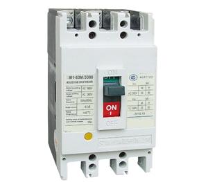
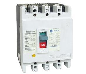
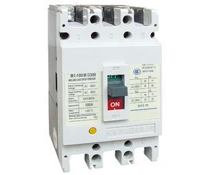
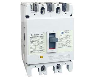
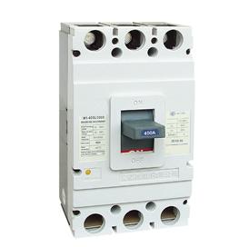
SM1 series moulded case circuit breaker is one of products developed and manufactured by adopting international advanced technology. It is supplied with rated insulating voltage 550 and 800V and used for circuit of AC 50/60Hz, rated operating voltage AC 400V (or below), rated operating current up to 1600A for infrequent changing over and starting of the motors.The products conforms to IEC60947-2 standard.
|
| |
| |
|
2. Main Technical Specification(table1) |
| |
| Type |
Rated
current (A) |
Polenum-ber |
Ratedinsui-atingvolt-age(V) |
Rated
operat-ingvolt-age(V) |
Arcing-
over
distance
(mm) |
Ultimate
short
circuit
breaking
capacity
(KA) |
Servies
short
circuit
breaking
capacity
(KA) |
Operation
perform-
ance |
Utiliza-tioncat-egory |
| Load |
Unload |
SM1-63L |
(6),10
16,20
25 ,32
40,50
63 |
3, 4 |
500V |
400V |
0 |
25 |
18 |
1500 |
8500 |
A |
SM1-63M |
0 |
50 |
35 |
SM1-100L |
(10),16
20,25
32,40
50,63
80,100 |
800V |
0(≤50) |
35 |
22 |
SM1-100M |
0(≤50) |
50 |
35 |
SM1-100H |
0(≤50) |
85 |
50 |
1000 |
7000 |
SM1-225L |
100,125
160,180
200,225 |
≤50 |
35 |
22 |
SM1-225M |
≤50 |
50 |
35 |
SM1-225H |
≤50 |
85 |
50 |
1000 |
4000 |
SM1-400L |
225,250
315,350
400 |
≤50 |
50 |
35 |
SM1-400M |
≤100 |
65 |
42 |
SM1-630L |
400,500
630 |
≤100 |
50 |
35 |
SM1-630M |
≤100 |
65 |
42 |
SM1-630H |
≤100 |
100 |
65 |
SM1-800M |
630,700
800 |
3 |
≤100 |
75 |
50 |
SM1-800H |
≤100 |
100 |
65 |
SM1-1250M |
1000,1250 |
≤100 |
100 |
65 |
SM1-1250H |
≤100 |
125 |
75 |
SM1-1600M |
1600 |
≤100 |
150 |
80 |
|
| |
|
Note: 6A without thermal protection
The N-pole of four-poles breaker is sited at the right side of the product has four types:
Type A: Without current trip-lease on N pole which making all the time, not closing and opening with the other three poles.
Type B: Without current trip-release on N pole which closing and opening with the other poles.
Type C: With current trip-release which closing and opening with the other three poles.
Type D: With current trip-release which making all the time not closing and opening with the other three poles.
|
| |
| |
|
3. Protection Characteristic |
| |
The thermodynamic release of a circuit breaker provides the feature of inverse time-delay, while the magnetic release is the instantaneous operation as shown on table 2(distribution circuit breaker) and table 3 (motor protection circuit breaker).
|
| |
|
Table2 |
| |
| Rated current of release (A) |
Thermodynamic release( ambient temperature ) land +40°C marine +45°C |
Operating current of magnetic release (A) |
| 1.05In(cold state) Inoperative time(h) |
1.30In(heat state) Operative time(h) |
| 10≤In≤63 |
≥ 1 |
< 1 |
10In±20% |
| 63<In≤100 |
≥ 2 |
< 2 |
| 100≤In≤800 |
≥ 2 |
< 2 |
5In±20% 10In±20% |
|
| |
|
Table3 |
| |
| Rated current |
Thermodynamic release ( ambient temperature ) land +40°C marine +45°C |
Operating current of magnetic release (A) |
| of release (A) |
1.0In(cold state) non-trip time(h) |
1.20In(heat state) trip time (h) |
1.50In(heat state) trip time (h) |
7.2In(cold state) trip time(h) |
| 10 ≤ In ≤ 225 |
≥ 2 |
<2 |
≤ 4min |
4s < Tp ≤ 10s |
12In±20% |
| 225 ≤ In ≤ 630 |
≤ 8min |
6s < Tp ≤ 20s |
|
| |
| |
|
4. Accessories of Circuit breaker |
| |
|
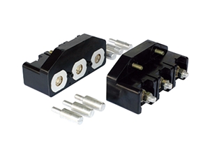
4.1 The external accessories of the breaker
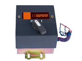
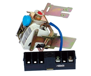
Motor-driven operation device
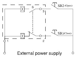
1) Wiring diagram of type CDM electromagnetic operation device(fitting AM1-63,100,225) seethe following drawing (wiring diagram of the external accessories of the breaker in the dotted frame) |
|
|
| |
Code description: SB1 SB2 stand for push button.(provided by users themselves) Number "1" "2" "3" stand for number of wiring terminals.
Voltage rating: AC50Hz 230V 400V DC 220V
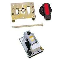
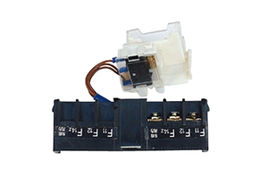
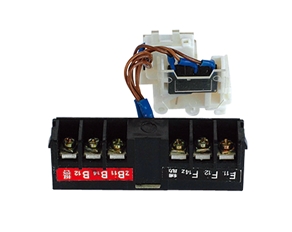
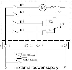
2) Wiring diagram of type CD motor-driven operation device (fitting SM1-400 630 800) seebelows (wiring diagram of the external accessories of the breaker in the dotted frame) |
| |
|
|
| |
|
Code description: SB1 SB2 stand for push button. (provided by users themselves) "X" stands for line connection terminals
Voltage rating: AC50Hz 230V 400V DC 220V |
| |
|
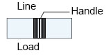
Rotary handle operation device
The mechanism is used in moulded case circuit breaker to operate the draw-out panel. Powerdistribution panel and supply box outside the panel by turning the handle ,and to ensure thedoor of panel would not be openned when the breaker being on. The hand-drive mechanism can be equiped with two types of operation, one is "A" modelsquare handle , the other is "B" model round handle. |
| |
|
|
| |
|
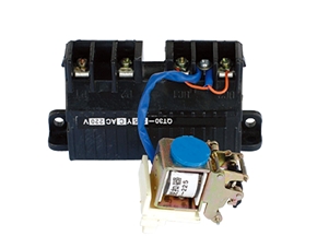
4.2 Release pattern and accessories code |
| |
|
|
| |
|
SHT: Shunt release; UVR: Under-voltage release;AX: Auxiliary contact; AL: Alarm contact |
| |
| Release patternand accessories code |
Name/Type |
SM1-63,
100, 225 |
SM1-400 |
SM1-630 |
SM1-800 |
| 200, 300 |
No accessories |
200: magnetic release (only short circuit protection)300: thermal magnetic release(both overload and short circuit protection) |
| 208, 308 |
Alarm contact |
|
|
|
|
| 210, 310 |
Shunt release |
|
|
|
|
| 220, 320 |
Auxiliary contact |
|
|
|
|
| 230, 330 |
Under-voltage release |
|
|
|
|
| 240, 340 |
Shunt release
Auxiliary contact |
|
|
|
|
| 250, 350 |
Shunt release
Under-voltage release |
|
|
|
|
| 260, 360 |
Two group of auxiliary contact |
|
|
|
|
| 270,370 |
Under-voltage release
Auxiliary contact |
|
|
|
|
| 218, 318 |
Shunt release
Alarm contact |
|
|
|
|
| 228, 328 |
Alarm contact Auxiliary contact |
|
|
|
|
| 238, 338 |
Under-voltage releaseAlarm contact |
|
|
|
|
| 248, 348 |
Shunt release, Alarm contact,Auxiliary contact |
|
|
|
|
| 268, 368 |
Two group of auxiliary contact,Alarm contact |
|
|
|
|
| 278, 378 |
Shunt release, Alarm contact, Under-voltage release |
|
|
|
|
|
| |
|
According to user's demands, accessories could lead to direct wire outcoming or line wiringterminals could be added(please mark out in case of making order). |
| |
|
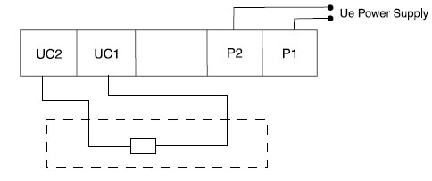
Under-voltage release
Wring diagram of the under-voltage module connected externally (the internal accessories inthe dotted frame)Ue: AC50Hz 230V, 400V |
| |
|
|
| |
|
When the operation voltage is 35%~70% of the rated voltage, the under-voltage release shouldmake the breaker trip correctly.When the operation voltage is 85%~110% of the rated voltage, the under-voltage release shouldmake the breaker close.In case of the operation voltage less than 35% of the rated voltage, the under-voltage shouldprevent the breaker from closing.Note: Only the under-voltage release should be energized in advanced, the breaker could berecramped and turned-on, otherwise the breaker will be damaged. |
| |
|
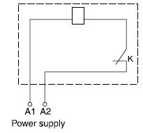
Shunt release
Scheme of wiring(the internal accessories in the dotted frame)"K" is the slow motion switch normal-close contact connect the coil in series in the shunt release.It turns-on or turns-off voluntarily as soon as the breaker on or off. |
| |
|
|
| |
|
Voltage rating: AC50Hz 230V or 400V, DC 110V 220VThe shunt release should make the breaker trip reliably when the operation voltage is 70%~110%of the rated control voltage. |
| |
|
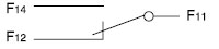
Alarm contact |
| The position of the breaker in "off" or "on" |
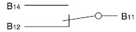 |
| The position of the breaker in "free trip" (alarm) |
B11 and B12 switch from "close" to "open", statusof B11 and B14 switch from "open" to "close" |
|
| |
|
Auxiliary Contact |
| When the breaker is in"off" |
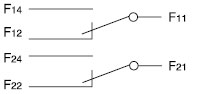 |
For the breaker with frame current400A and above |
 |
For the breaker with frame current225A and below |
| When the breaker is in"on" |
When the breaker is in "off", the contacts switch from "close" to "open".When the breaker is in "off",the contacts switch from "open"to close" |
|
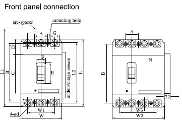
| |
| Type |
Outline Dimensions(mm) |
| Front panel connection |
| W |
W1 |
L |
L1 |
L2 |
H |
H1 |
H2 |
H3 |
H4 |
C |
D |
E |
F |
G |
W2 |
W3 |
SM1-63L |
76 |
50 |
135 |
170 |
117 |
74 |
92 |
|
7 |
4 |
85 |
28.5 |
48 |
22 |
14 |
100 |
75 |
SM1-63M |
76 |
50 |
135 |
170 |
117 |
82 |
98.5 |
28 |
7 |
4 |
85 |
28.5 |
48 |
22 |
14 |
100 |
75 |
SM1-100L |
92 |
60 |
150 |
185 |
132 |
68 |
86 |
24 |
7 |
4 |
88 |
35.5 |
50 |
22 |
17.5 |
|
|
SM1-100M |
92 |
60 |
150 |
185 |
132 |
86 |
104 |
24 |
7 |
4 |
88 |
35.5 |
50 |
22 |
17.5 |
122 |
90 |
SM1-100H |
92 |
60 |
150 |
185 |
132 |
86 |
104 |
24 |
7 |
4 |
88 |
35.5 |
50 |
22 |
17.5 |
|
|
SM1-225L |
107 |
70 |
165 |
215 |
144 |
86 |
110 |
24 |
5 |
4 |
102 |
31.5 |
50 |
22 |
17 |
|
|
SM1-225M |
107 |
70 |
165 |
215 |
144 |
103 |
127 |
24 |
5 |
4 |
102 |
31.5 |
50 |
22 |
17 |
142 |
105 |
SM1-225H |
107 |
70 |
165 |
215 |
144 |
103 |
127 |
24 |
5 |
4 |
102 |
31.5 |
50 |
22 |
17 |
|
|
SM1-400L |
150 |
96 |
257 |
357 |
224 |
105 |
155 |
38 |
8 |
6 |
128 |
64.5 |
89 |
65 |
φ6 |
198 |
144 |
SM1-400M |
182 |
116 |
270 |
370 |
234 |
110 |
160 |
43 |
8 |
6 |
134 |
70 |
89 |
65 |
φ9 |
|
|
SM1-630L |
182 |
116 |
270 |
370 |
234 |
110 |
160 |
43 |
8 |
6 |
134 |
70 |
89 |
65 |
φ9 |
240 |
174 |
SM1-630M |
182 |
116 |
270 |
370 |
234 |
110 |
160 |
43 |
8 |
6 |
134 |
70 |
89 |
65 |
φ9 |
|
|
SM1-630H |
210 |
140 |
280 |
380 |
243 |
106 |
145 |
33 |
30 |
128 |
|
|
|
|
|
|
|
SM1-800M |
210 |
140 |
280 |
380 |
243 |
106 |
145 |
33 |
30 |
128 |
|
|
|
|
|
|
|
SM1-800H |
210 |
140 |
280 |
380 |
243 |
106 |
145 |
33 |
30 |
128 |
|
|
|
|
|
|
|
SM1-1250M |
210 |
140 |
393 |
|
|
200 |
|
|
|
|
|
|
|
|
|
|
|
SM1-1250H |
210 |
140 |
393 |
|
|
200 |
|
|
|
|
|
|
|
|
|
|
|
SM1-1600M |
210 |
140 |
393 |
|
|
200 |
|
|
|
|
|
|
|
|
|
|
|
|
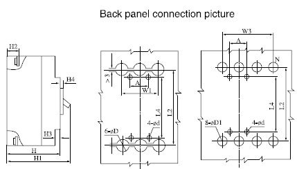
| |
| Type |
Outline Dimensions(mm) |
Installation
Dimensions |
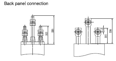
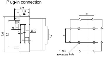
| Back panel connection |
Plug-in connection |
| L4 |
H5 |
H6 |
φD |
φD1 |
L5 |
L6 |
H7 |
H8 |
H9 |
H10 |
J |
K |
φd1 |
M |
A |
B |
φd |
SM1-63L |
117 |
44 |
66 |
8 |
8 |
|
|
|
|
|
|
|
|
|
|
25 |
117 |
3.5 |
SM1-63M |
117 |
44 |
66 |
8 |
8 |
|
|
|
|
|
|
|
|
|
|
25 |
117 |
3.5 |
SM1-100L |
129 |
68 |
108 |
26 |
16 |
92 |
168 |
50 |
62 |
74 |
17.5 |
56 |
60 |
6.5 |
M8 |
30 |
129 |
4.5 |
SM1-100M |
129 |
68 |
108 |
26 |
16 |
92 |
168 |
50 |
62 |
74 |
17.5 |
56 |
60 |
6.5 |
M8 |
30 |
129 |
4.5 |
SM1-100H |
129 |
68 |
108 |
26 |
16 |
92 |
168 |
50 |
62 |
74 |
17.5 |
56 |
60 |
6.5 |
M8 |
30 |
129 |
4.5 |
SM1-225L |
126 |
66 |
110 |
20 |
20 |
94 |
183 |
50 |
69.5 |
84.5 |
17.5 |
54 |
70 |
6.5 |
M8 |
35 |
126 |
5 |
SM1-225M |
126 |
66 |
110 |
20 |
20 |
94 |
183 |
50 |
69.5 |
84.5 |
17.5 |
54 |
70 |
6.5 |
M8 |
35 |
126 |
5 |
SM1-225H |
126 |
66 |
110 |
20 |
20 |
94 |
183 |
50 |
69.5 |
84.5 |
17.5 |
54 |
70 |
6.5 |
M8 |
35 |
126 |
5 |
SM1-400L |
194 |
60 |
120 |
33 |
33 |
169 |
279 |
60 |
83.5 |
106.5 |
21 |
129 |
60 |
8.5 |
M10 |
44 |
194 |
7 |
SM1-400M |
200 |
65 |
125 |
36 |
36 |
169 |
299 |
60 |
92 |
110 |
21 |
123 |
100 |
8.5 |
M12 |
58 |
200 |
7 |
SM1-630L |
200 |
65 |
125 |
36 |
36 |
169 |
299 |
60 |
92 |
110 |
21 |
123 |
100 |
8.5 |
M12 |
58 |
200 |
7 |
SM1-630M |
200 |
65 |
125 |
36 |
36 |
169 |
299 |
60 |
92 |
110 |
21 |
123 |
100 |
8.5 |
M12 |
58 |
200 |
7 |
SM1-630H |
|
128 |
|
|
|
|
|
|
|
|
|
|
|
|
|
70 |
243 |
7.2 |
SM1-800M |
|
128 |
|
|
|
|
|
|
|
|
|
|
|
|
|
70 |
243 |
7.2 |
SM1-800H |
|
128 |
|
|
|
|
|
|
|
|
|
|
|
|
|
70 |
243 |
7.2 |
SM1-1250M |
|
|
|
|
|
|
|
|
|
|
|
|
|
|
|
|
|
|
SM1-1250H |
|
|
|
|
|
|
|
|
|
|
|
|
|
|
|
|
|
|
SM1-1600M |
|
|
|
|
|
|
|
|
|
|
|
|
|
|
|
|
|
|
|
| |
| |
le> SM1-1250H 210 140 393 200 AM1-1600M 210 140 393 200 |
| Type |
Outline Dimensions(mm) |
Installation
Dimensions |
| Back panel connection |
Plug-in connection |
| L4 |
H5 |
H6 |
φD |
φD1 |
L5 |
L6 |
H7 |
H8 |
H9 |
H10 |
J |
K |
φd1 |
M |
A |
B |
φd |
SM1-63L |
117 |
44 |
66 |
8 |
8 |
|
|
|
|
|
|
|
|
|
|
25 |
117 |
3.5 |
SM1-63M |
117 |
44 |
66 |
8 |
8 |
|
|
|
|
|
|
|
|
|
|
25 |
117 |
3.5 |
SM1-100L |
129 |
68 |
108 |
26 |
16 |
92 |
168 |
50 |
62 |
74 |
17.5 |
56 |
60 |
6.5 |
M8 |
30 |
129 |
4.5 |
SM1-100M |
129 |
68 |
108 |
26 |
16 |
92 |
168 |
50 |
62 |
74 |
17.5 |
56 |
60 |
6.5 |
M8 |
30 |
129 |
4.5 |
SM1-100H |
129 |
68 |
108 |
26 |
16 |
92 |
168 |
50 |
62 |
74 |
17.5 |
56 |
60 |
6.5 |
M8 |
30 |
129 |
4.5 |
SM1-225L |
126 |
66 |
110 |
20 |
20 |
94 |
183 |
50 |
69.5 |
84.5 |
17.5 |
54 |
70 |
6.5 |
M8 |
35 |
126 |
5 |
SM1-225M |
126 |
66 |
110 |
20 |
20 |
94 |
183 |
50 |
69.5 |
84.5 |
17.5 |
54 |
70 |
6.5 |
M8 |
35 |
126 |
5 |
SM1-225H |
126 |
66 |
110 |
20 |
20 |
94 |
183 |
50 |
69.5 |
84.5 |
17.5 |
54 |
70 |
6.5 |
M8 |
35 |
126 |
5 |
SM1-400L |
194 |
60 |
120 |
33 |
33 |
169 |
279 |
60 |
83.5 |
106.5 |
21 |
129 |
60 |
8.5 |
M10 |
44 |
194 |
7 |
SM1-400M |
200 |
65 |
125 |
36 |
36 |
169 |
299 |
60 |
92 |
110 |
21 |
123 |
100 |
8.5 |
M12 |
58 |
200 |
7 |
SM1-630L |
200 |
65 |
125 |
36 |
36 |
169 |
299 |
60 |
92 |
110 |
21 |
123 |
100 |
8.5 |
M12 |
58 |
200 |
7 |
SM1-630M |
200 |
65 |
125 |
36 |
36 |
169 |
299 |
60 |
92 |
110 |
21 |
123 |
100 |
8.5 |
M12 |
58 |
200 |
7 |
SM1-630H |
|
128 |
|
|
|
|
|
|
|
|
|
|
|
|
|
70 |
243 |
7.2 |
SM1-800M |
|
128 |
|
|
|
|
|
|
|
|
|
|
|
|
|
70 |
243 |
7.2 |
SM1-800H |
|
128 |
|
|
|
|
|
|
|
|
|
|
|
|
|
70 |
243 |
7.2 |
SM1-1250M |
|
|
|
|
|
|
|
|
|
|
|
|
|
|
|
|
|
|
SM1-1250H |
|
|
|
|
|
|
|
|
|
|
|
|
|
|
|
|
|
|
SM1-1600M |
|
|
|
|
|
|
|
|
|
|
|
|
|
|
|
|
|
|
|
| |
|
|
| |
|
|
| |
| |
|
|
| |
| |
|
|
|
|